Toolbox Foam Cutouts
The steps below describe a manual process that worked for us for a number of our toolbox drawers. We’ve added a few more drawers since the below process was developed and found https://shadowbox.tools/ which streamlined the process. We had the best results with the Paper Trace method. We have also been recommended Took Kaiser but have not used it for a drawer yet.
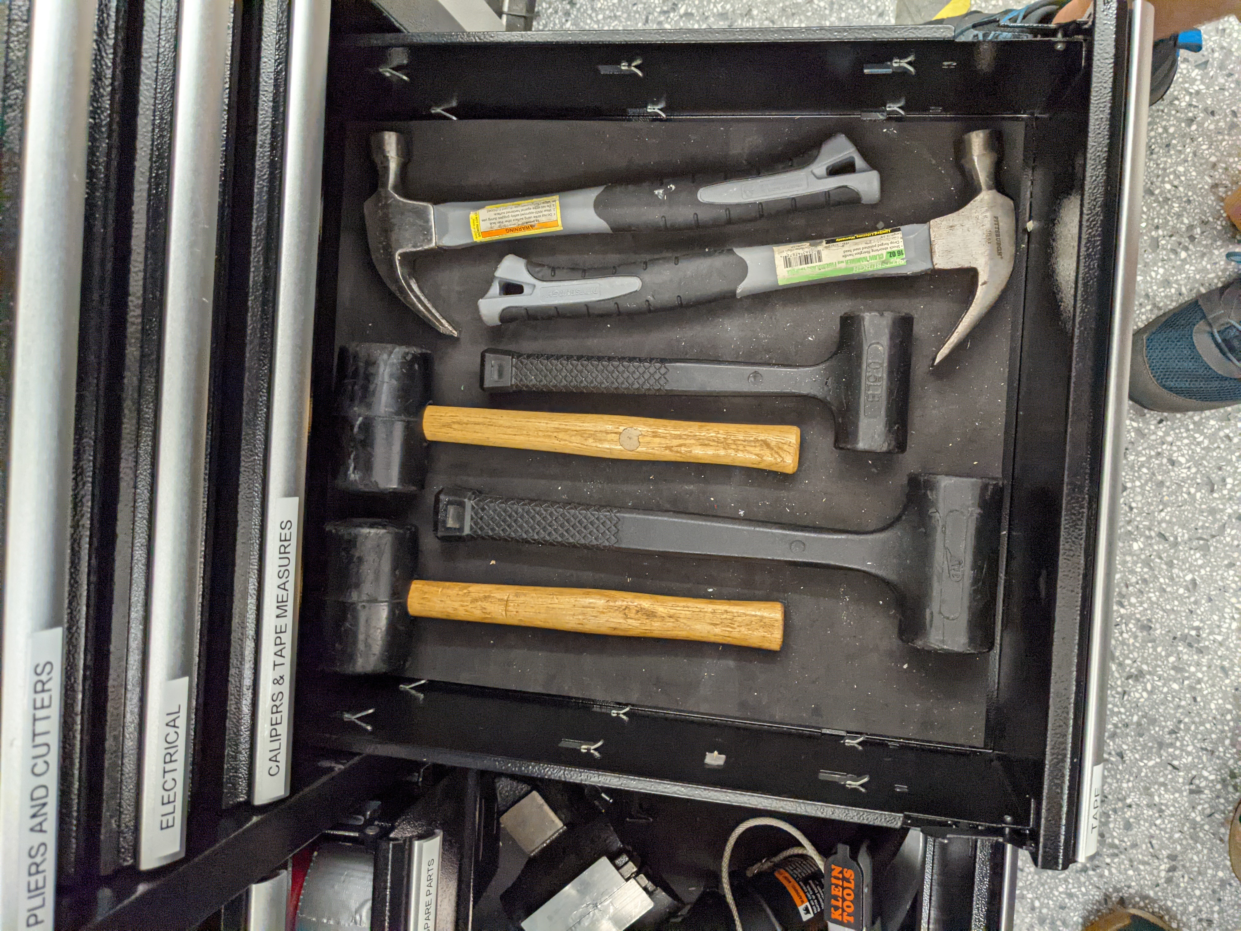
- Start by making a rough layout

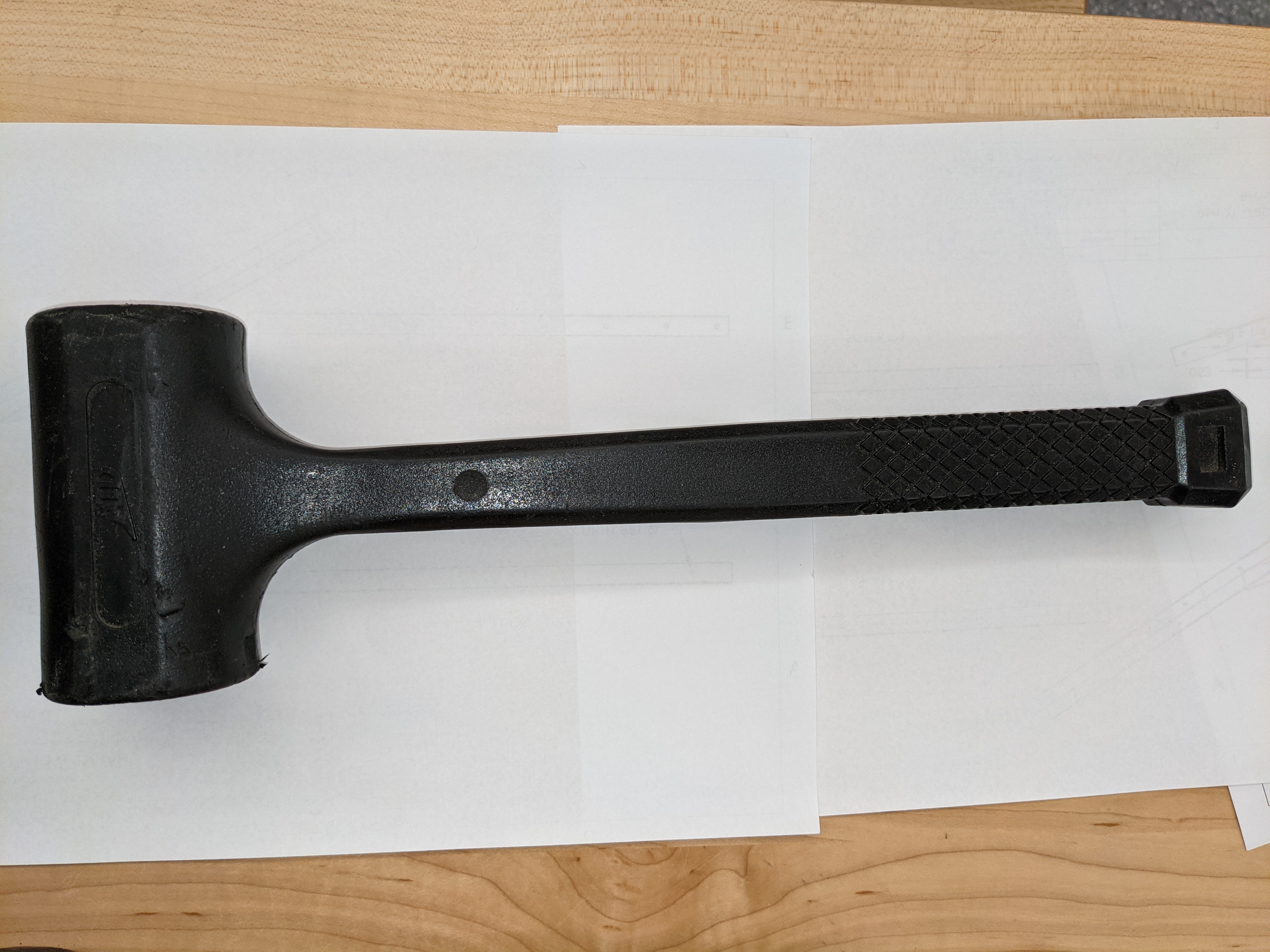
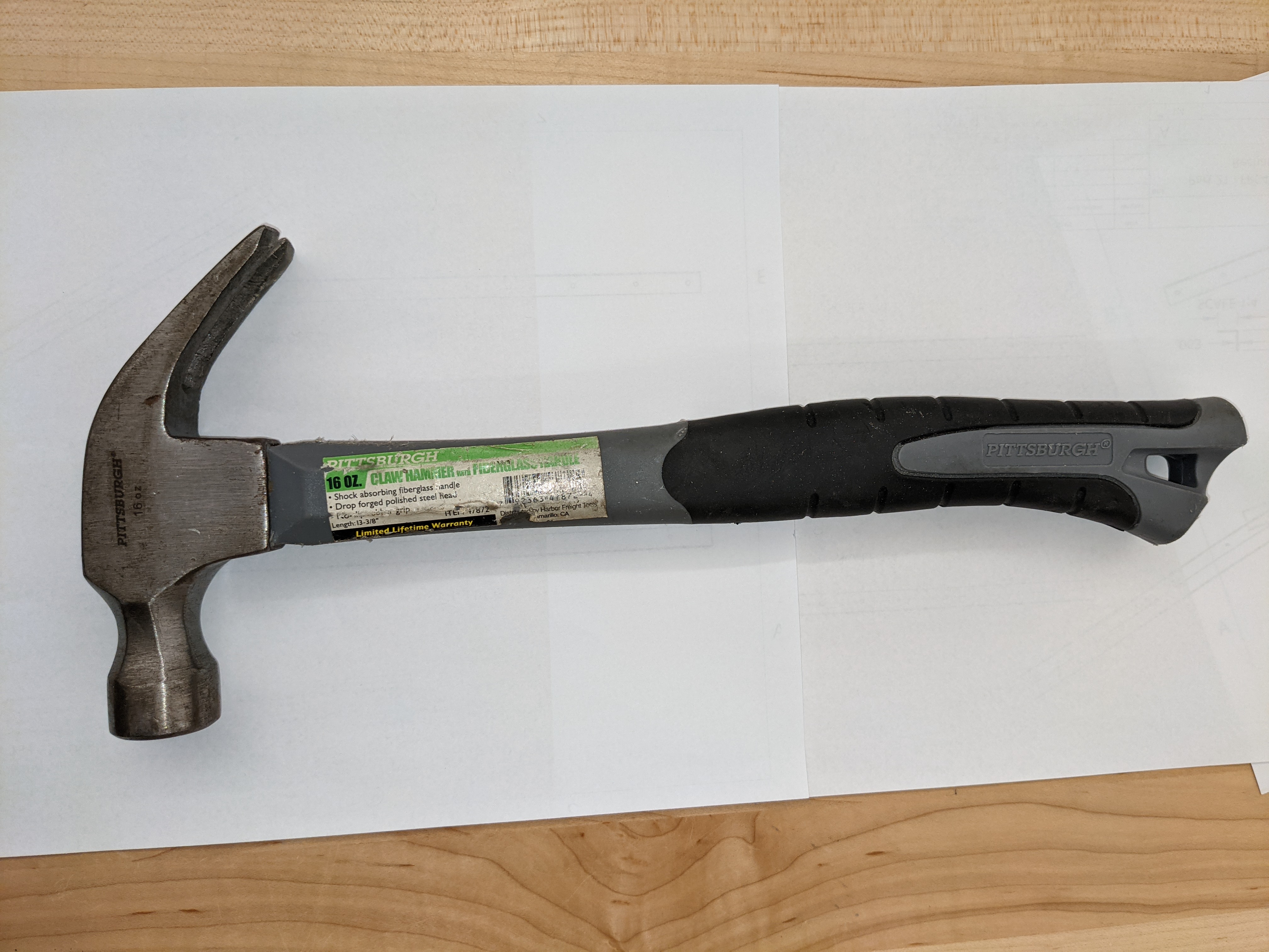
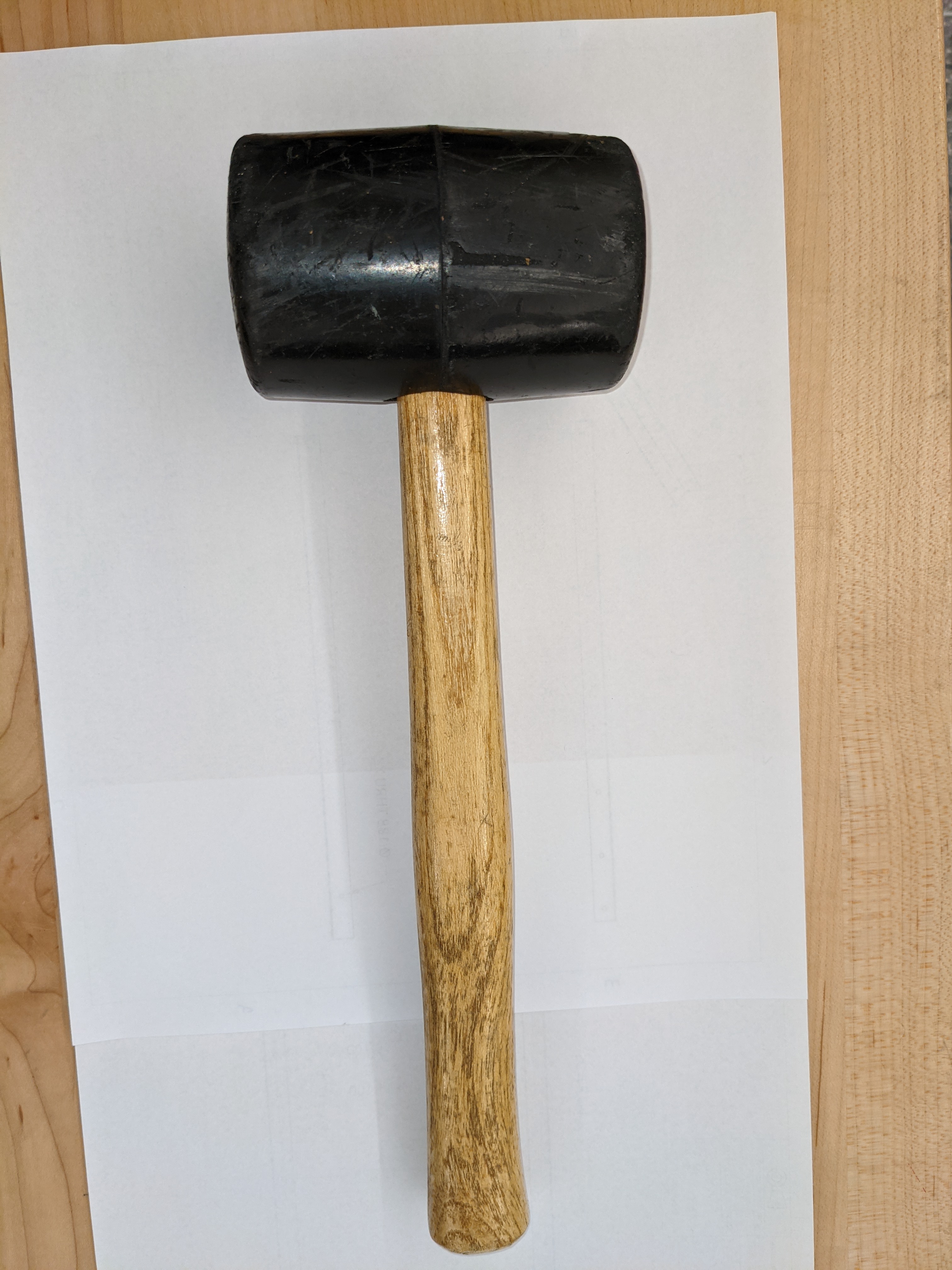
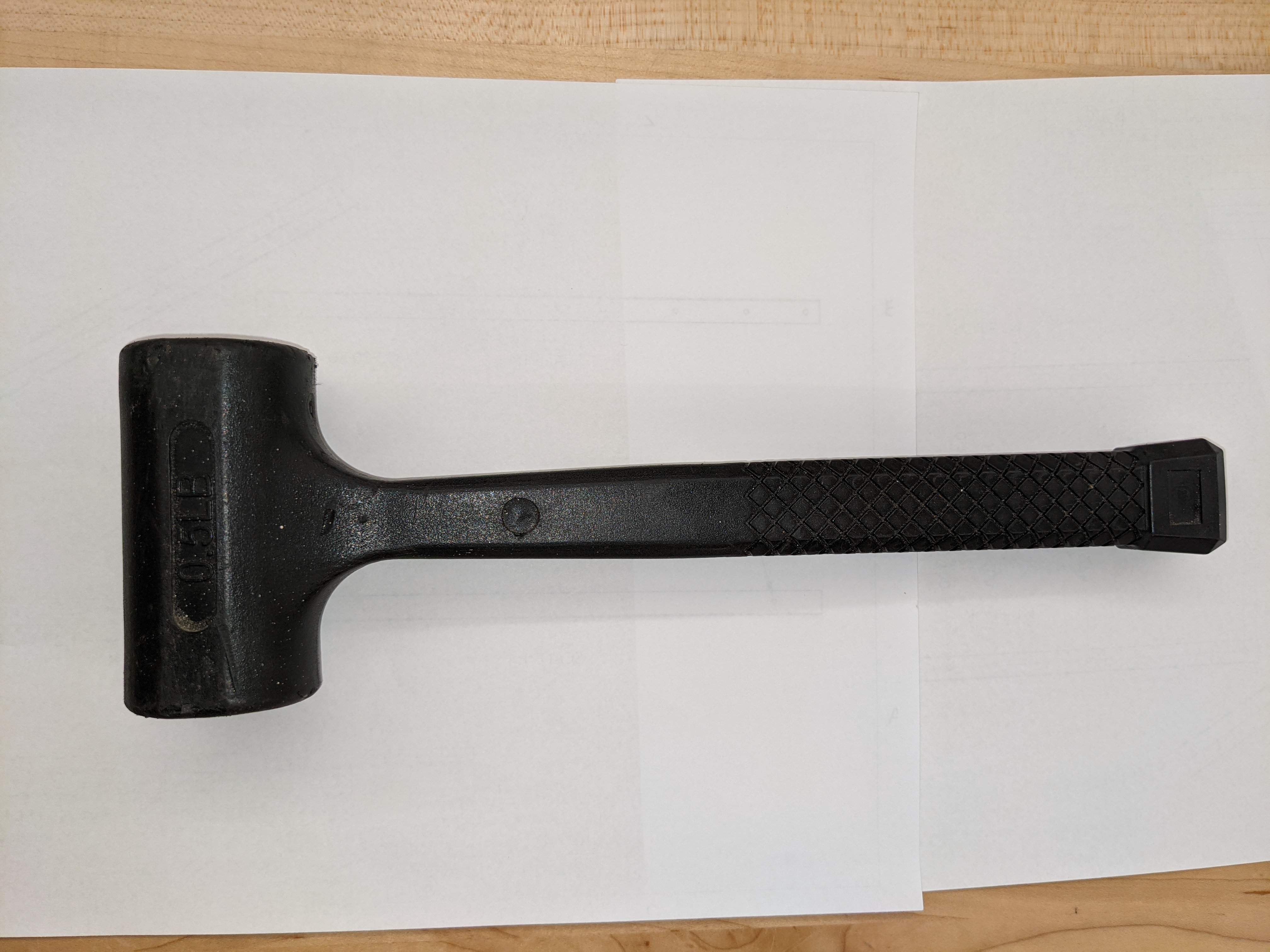
- Take photos of each of the tools, ensure you have plenty of contrast

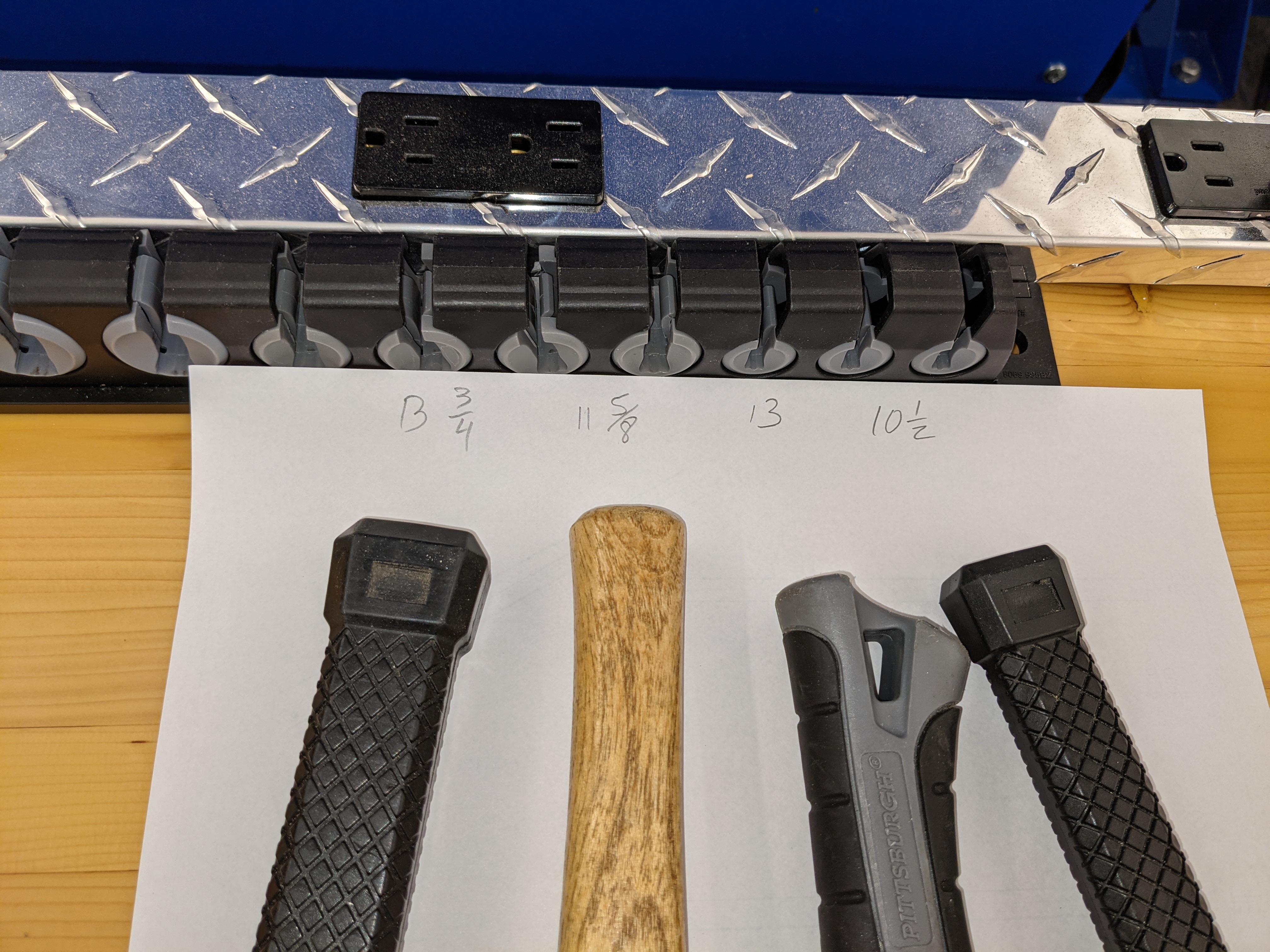
- Measure the longest axis of each tool so we can properly scale the images later
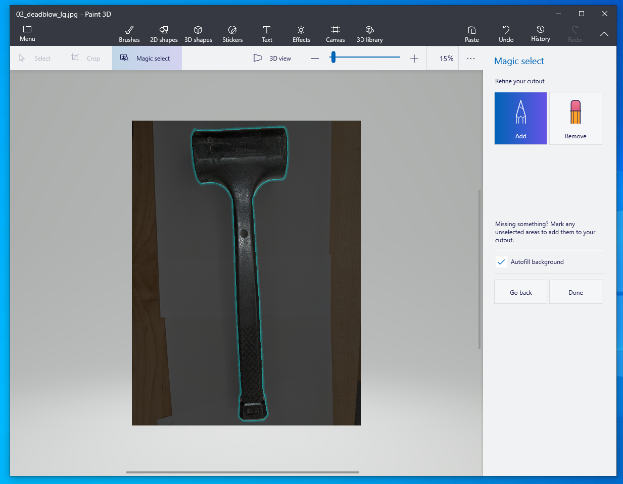
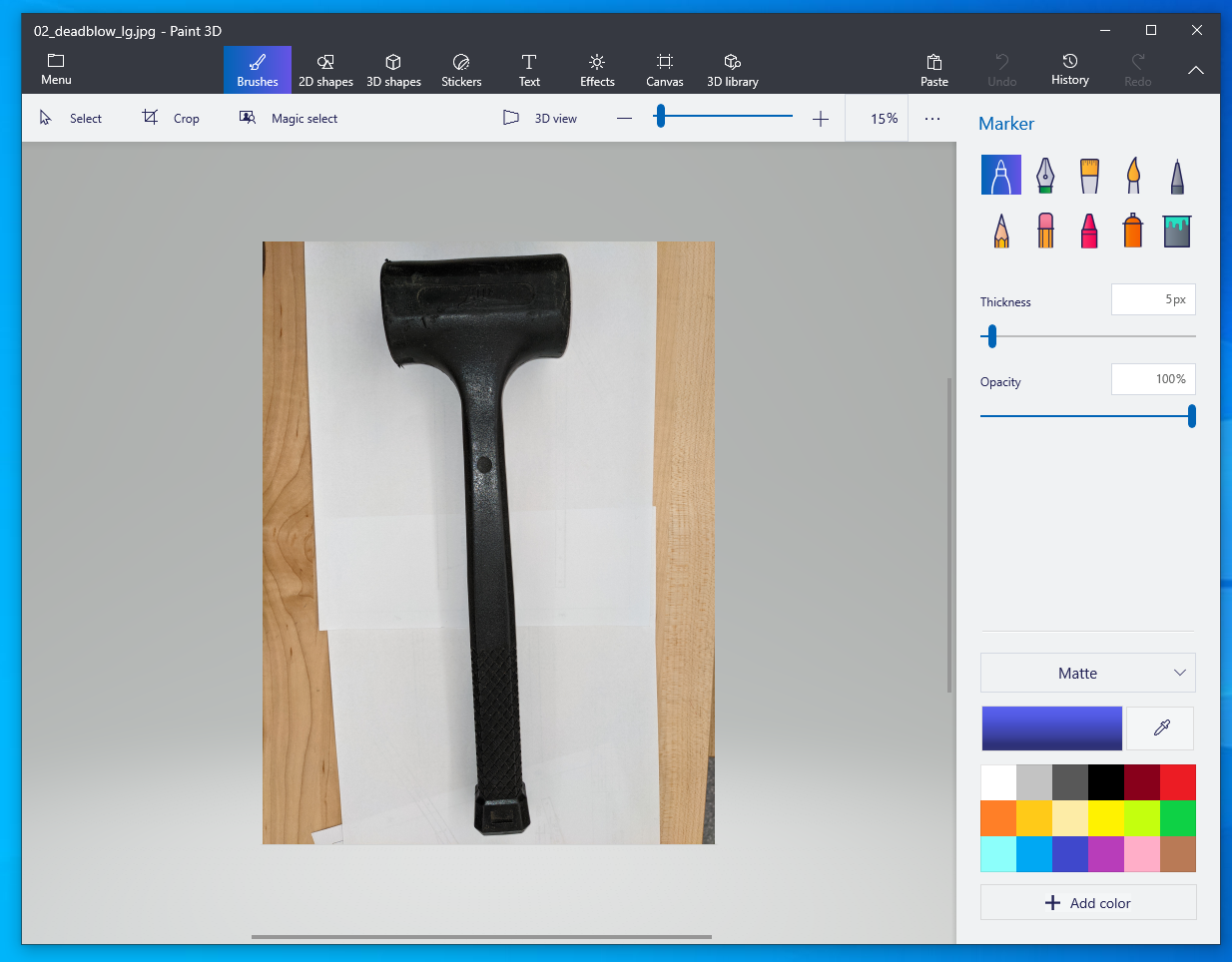
- To remove the background, open image in paint3d

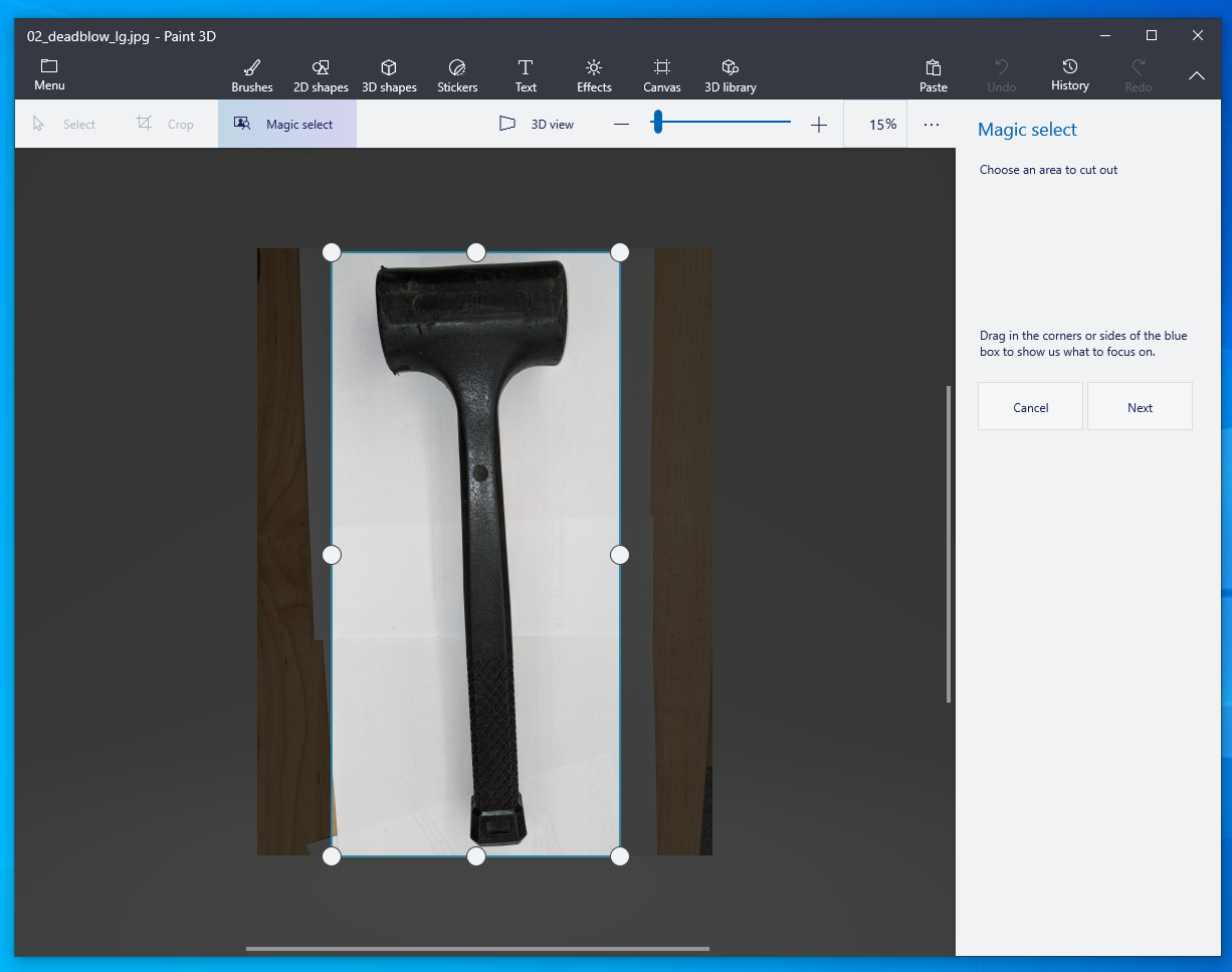
- Use the Magic Select tool, drag the handles to remove as much background as possible

- If you need to refine the selection, Use the Pencil and Eraser to mark parts to keep and parts to remove respectively.
- Copy the tool selection and paste in Inkscape. Repeat for all tools, create a layout matching your rough layout from step 1.

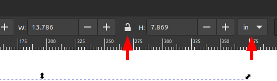
- Use the Width and Height toolbar in Inkscape to ensure your tool is the proper size using the measurements from earlier. Be sure to click the lock icon to ensure the with and height aspect ratio is maintained.
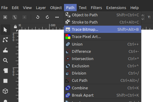
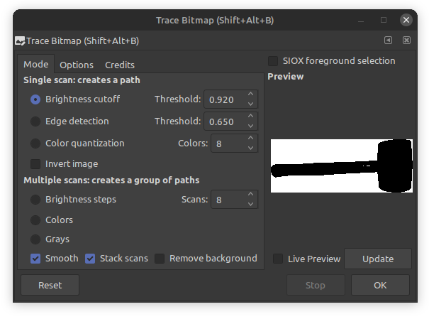
- Use Inkscape’s bitmap trace function to convert the tools to vector paths.


We’ve found that the Brightness cutoff with a threshold of .92 or higher works well. If you go too high the results are not as good.
Once you have traced each image, it is safe to delete the original image.
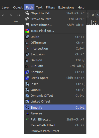
- The trace tool may leave sharp edges or other imperfections that we need to remove. We’ll simplify the generated path to make it easier to work with. Select each tool outline and use the simplify option.


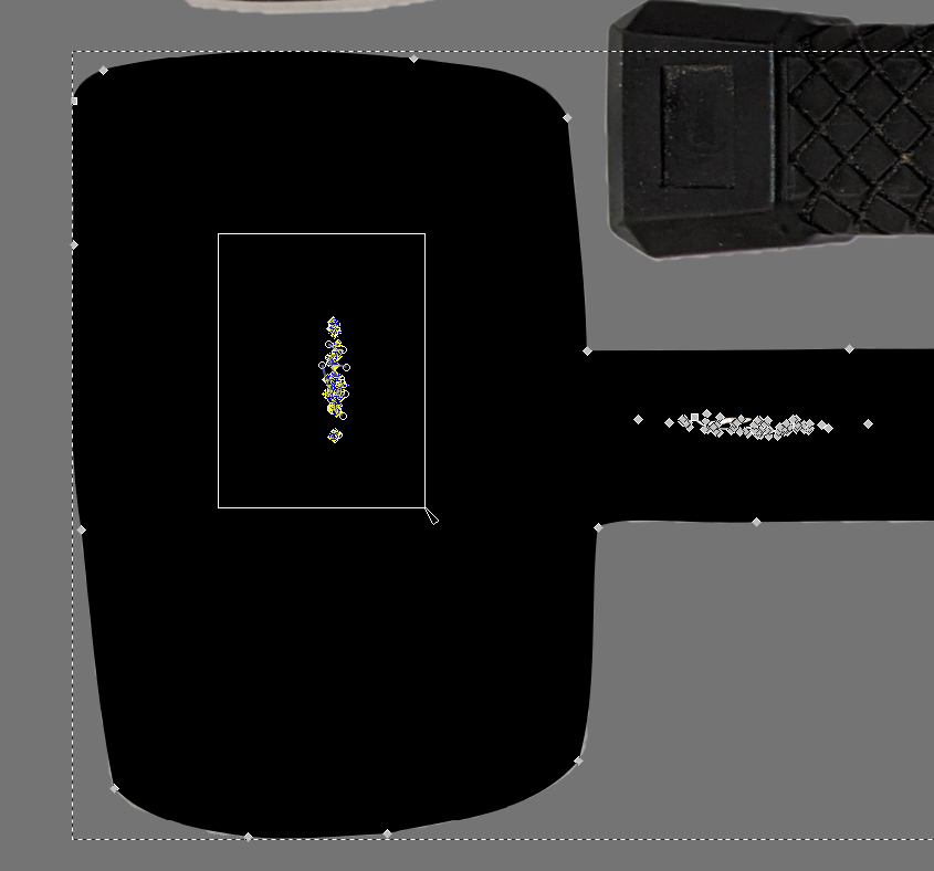
- To cleanup any last imperfections, zoom in on each tool and double click. Now we can edit the nodes on the path. Select and delete any that should not be cut. Simplify doesn’t always do exactly what we want, but you can manually adjust the nodes. We’ve found making the path transparent allows one to see the tool image below and adjust if needed.
 Final Result:

- We added slots to make it easier to get the tools out.
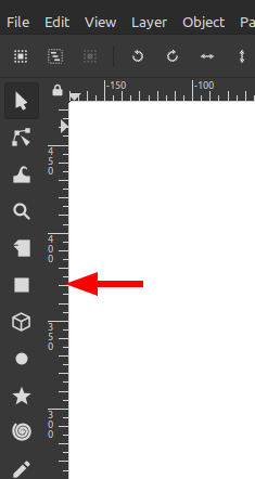
Use the rectangle tool to create a rectangle across a convenient area to grasp the tool, without compromising the foam’s ability to hold the tool.

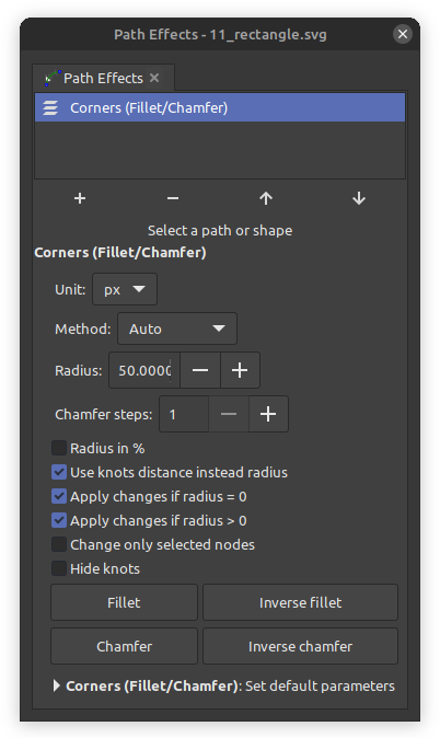
- We added a chamfer to the rectangle for astethic reasons.

- Combine the individual paths into a single path using the union tool
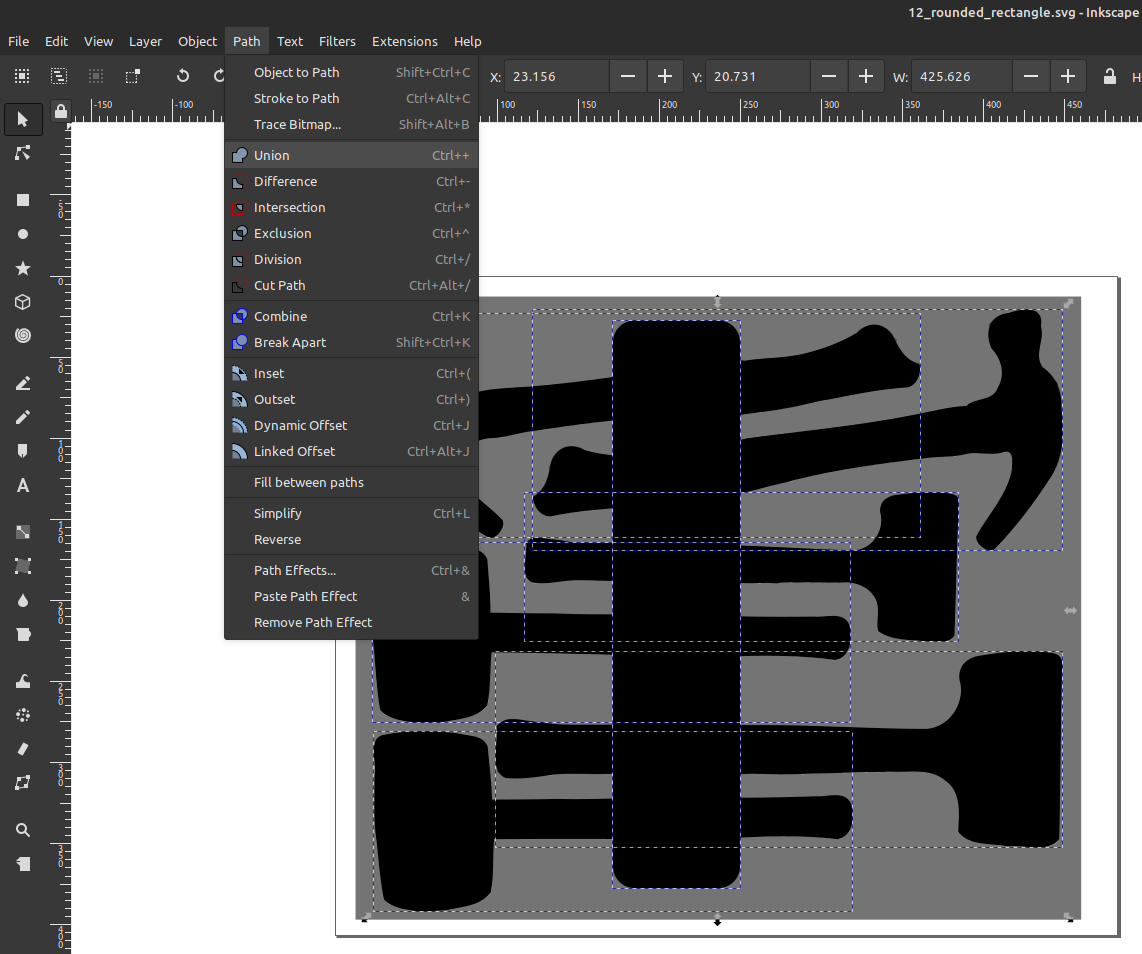
- Remove fill for cutting


- Make sure the path is selected, then
- From the
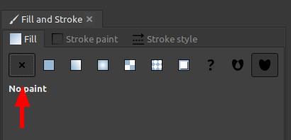
Objectmenu chooseFill and Stroke - Choose
No paint
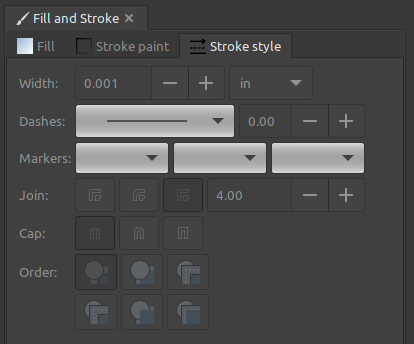
- For our Epilog laser we need a stroke width of .001" for cutting
- From the
Stroke Styletab change the width unit toinand change the width to.001 - At this point it may look like your drawing is missing, but the lines are too thin to render unless you zoom in.

- Export for cutting
- Choose File > Save As…
- Be sure to choose PDF
- [Cut it!](/tutorials/laser-cutter-intro//#preparing-the-file)